Order-Independent Transparency With AtomicusChart®
Rendering fully opaque objects (objects with no translucent parts) is a trivial task that can be accomplished with the help of a depth buffer. The idea is that each slot of the render surface (typically called a pixel) reserves data not only for color (for example, the RGBA32 format is 4 bytes per pixel), but also for depth of the fragment that is currently contained at the pixel location (it is an additional 4 bytes per pixel by default).
During the rendering process, the graphics card computes the total depth of the fragment (far objects get higher values and nearer objects get lower ones), so if the depth value of an already rendered point is smaller than that of a pending point, the one with the greater depth value is discarded from the frame because it is hidden from our sight. The depth buffer is a hardware-supported feature, so, luckily for users, it has almost no impact on visualization performance.
Unfortunately, translucent object rendering isn't quite so easy. The problem is that colors provided as an output of the rendering process must be merged from farthest to closest using a special blending algorithm (a linear interpolation operation by default) to achieve the expected result.
But we cannot use depth buffer here because it would discard a lot of translucent fragments. So the most logical, most popular, and quickest solution to this problem is called “order-dependent transparency.”
The idea is to sort all the visible translucent objects by their depth values (typically, the transformed center of the object's bounding box) before rendering them. It sounds great, but only works when an object has no multiple points that might theoretically be projected on the same point of the screen, or when translucent objects have no intersections.
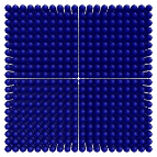
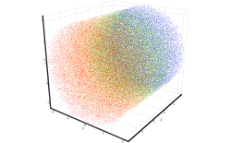
The reason is that we have sorted the objects, but we have not provided the identical mechanism for the points that are contained within them (for example, a point cloud is presented as a single render object, but has a number of “internal parts”). Here is an example:
| Result: 57.6 FPS |
|---|

|
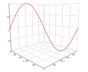
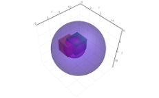
As you can see, the chart includes two cubes and a sphere with internal intersections inside a larger sphere. You might also notice that the order of the objects' color blending is incorrect. Here is another example of the same scene with a slightly rotated camera view:
| Result: 1436.4 FPS |
|---|

|
Now we can see the real objects' colors, and the result is even more unusual for users, but we cannot expect more from order-dependent transparency for the reasons mentioned above.
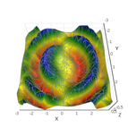
An algorithm called "order-independent transparency" (OIT) makes the chart pictured above possible. The order-independent transparency technique is based on a modified order-independent transparency algorithm with the help of a per-pixel linked list. The solution for the transparent objects rendering task is to store any visible translucent object output fragment color and depth during the rendering pre-pass, and to blend them from farthest to nearest at the merge stage. This mechanism provides the best rendering results but requires much higher performance, has a larger resource impact, and comes with limitations. As it requires substantial graphical resources, an alternative technique of translucent object visualization (suitable for cases where there is no surface intersection and object blending) is implemented as well. Default implementation is designed to handle 10 fragments per pixel location. For example, for a 1920 x 1080p screen resolution, storage is provided only for 1920 x 1080 x 10 fragments. Fragments that are out of this range will be discarded, producing a render output error.
Examples of the Order-Independent Transparency Feature
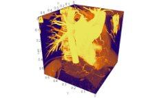
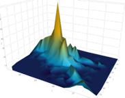
Volume rendering provides a convenient technique for visualization of 3D data sets. Its algorithm is called “volume ray casting.” During the implementation of this technique, the ray attached in the specific direction with a predefined step value moves while blended colors are extracted from the color legend.
According to the information above, the fragments located behind the entry points will be discarded. Other object parts located within the volume bounds will be invisible by default.
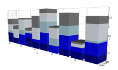
| Volume depth test |
|---|

|
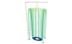
Another AtomicusChart®-supported technique called the "volume depth test” corrects the ray casting exit point according to the current state of the depth buffer. This technique has one strong limitation: Opaque objects' render data must be located before the volume ray casting render data in the chart data source collection to ensure that the depth buffer is in the correct state before volume rendering.
Unfortunately, this technique is not suitable for rendering translucent objects because its fragments are not being stored in a depth buffer.
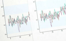
1. MSAA Disabled

2. МSАА 2х

3. МSАА 4х

4. МSАА 8х

5.SSAA

6. SSAA+МSАА8х